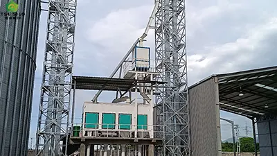
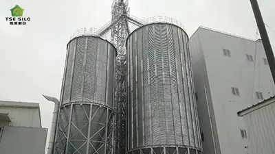
As a core facility in modern bulk grain storage, grain steel silos rely on their accompanying drive motor systems for all grain discharge, transfer, and ventilation operations. The motor base—serving as the critical load-bearing component connecting the power source to the silo's foundation—has an operational stability that directly impacts the entire silo's conveying efficiency and equipment safety. However, in actual production environments, excessive vibration of the motor base is one of the most common equipment malfunctions encountered. In mild cases, this leads to loosened anchor bolts and accelerated wear on couplings; in severe cases, it can trigger foundation cracking, damage to motor windings, or even necessitate a forced shutdown for repairs. Accurately identifying the root causes of base vibration and establishing a systematic logic for fault analysis are prerequisites for ensuring the safe and continuous operation of steel silos. Drawing upon both field experience and the principles of mechanical dynamics, this article summarizes six major typical causes of such vibration and analyzes each in detail, aiming to provide equipment maintenance personnel with actionable diagnostic guidelines.


1. Causes of Looseness in Installation, Fixation, and Base Structure, and Basic Requirements
1.1. Causes of Looseness
- Motor Anchor Bolts: Subjected to long-term impact from motor starts, stops, and load fluctuations, anchor bolts may suffer from loosened nuts, stripped threads, or aged and collapsed washers.
- Silo Support Framework: The steel plate welds on the silo's auxiliary equipment racks or motor bases may crack, or the channel steel supports may deform; this results in the base's contact surface becoming suspended (not making full contact) or subject to uneven load distribution.
- Foundation Leveling Failure: The foundation leveling may fail, resulting in rigid contact between the base and the foundation without any vibration-damping buffer; this allows operational resonance to amplify the amplitude of the vibration.
1.2. Requirements for Foundation and Base Structure
- Base Material and Rigidity: The motor mounting base must be fabricated by welding channel steel, I-beams, or thickened steel plates; the main plate thickness must be >= 8 mm, and the load-bearing stiffeners must be >= 6 mm thick. The overall frame must be free of deformation or twisting, with a straightness tolerance of <= 3 mm/m.
- Foundation Flatness: The deviation in the levelness of the base's mounting contact surface must be <= 0.5 mm/m, with a cumulative overall height difference tolerance of <= 2 mm. Installation methods involving suspension (gaps), single-point loading, or angled/warped contact are strictly prohibited.
- Structural Welding Strength: All full-penetration welds on the base must have a height of >=5 mm and be free of slag inclusions, incomplete fusion, cracks, or porosity. The brackets and reinforcing ribs must be securely welded, and the overall structure's resistance to vibration loads must satisfy the requirements for continuous 24-hour operation.
1.3. Technical Parameters for Anchor Bolt Fixing
- Bolt Specifications and Material: The accompanying anchor bolts shall be Grade 8.8 high-strength bolts. For standard motors, the bolt size shall be >= M12; for high-power/heavy-duty motors (above 15 kW), the size shall be >= M16.
- Tightening Torque Standards: The standard tightening torque for M12 bolts is 45–55 N·m; for M16 bolts, it is 80–95 N·m.
- Washer and Anti-loosening Configuration: Each bolt assembly must be configured with a flat washer, a spring washer, and a double-nut anti-loosening mechanism. The compression of the spring washer must reach its standard deformation level; missing washers, the mixing of thin washers, or the use of damaged washers is strictly prohibited. Anti-slip metal plates shall be installed at contact surfaces to prevent slippage caused by prolonged vibration.
- Bolt Reservation and Embedding: The verticality deviation of embedded anchor bolts shall be <= 1.5°. The exposed thread length shall be 2–3 threads, and the threads must be intact, free of stripping, and free of corrosion.
1.4. Vibration Damping and Cushioning Installation Requirements
- Selection and Installation of Damping Components: The bottom of the motor shall be equipped with standard rubber damping pads or vibration isolators. The compression of the damping pads shall be controlled within the range of 20% to 30%. The use of aged, cracked, or hardened damping pads—as well as missing pads or the stacking of multiple layers—is strictly prohibited.
- Contact Surface Requirements: The bottom surface of the motor frame must be in full contact with the damping pads, and the damping pads must be in full contact with the base plate surface. The allowable gap is <= 0.3 mm, with no localized suspension or uneven contact.
1.5. Requirements for Brackets and Connection Structures
- Bracket Deformation Limits: Under the motor's rated operating load, the static deflection of the bracket shall be <= 1/1000. Under load impact conditions, no plastic deformation is permitted.
- Splicing and Securing: For split-type bases, splicing seams must be aligned, and all connecting bolts must be fully installed and tightened; seam misalignment shall not exceed 1 mm. For motor brackets mounted on the silo wall, the anchoring depth of expansion bolts must be >= 100 mm.
1.6. Acceptance and Routine Tightening Standards
- Static Tightening Acceptance: Upon completion of equipment installation, a 100% random inspection of the torque on all anchor bolts shall be conducted, with a permissible looseness rate of 0%.
- Periodic Tightening Requirements: Newly installed equipment—a comprehensive re-tightening must be performed after 72 hours of operation. Standard operating conditions—bolt torque must be re-inspected monthly. Conditions involving heavy dust, heavy loads, or continuous operation—re-inspection must be performed every 15 days.
- Criteria for Determining Looseness: If a bolt exhibits visible displacement to the naked eye, shows a gap when pried with a wrench, or has a torque value falling more than 15% below the standard value, it is deemed a potential loosening hazard and must be rectified immediately.
2. Coaxiality Deviation between Motor and Load Equipment
Grain steel silos are typically paired with equipment such as scraper conveyors, bucket elevators, and discharge augers; issues may arise involving coupler eccentricity, misalignment, or wear and cracking of buffer pads.
If the motor shaft is not concentric with the shafts of the reducer or conveying equipment, radial torque is generated during operation. This torque is transmitted directly to the motor base, inducing periodic vibration which, over the long term, can lead to the structural failure (tearing) of the base's mounting components.
2.1. Radial Deviation (Circumferential Concentricity)
- Static (Cold State) Installation Standard: Radial runout deviation must be less than 0.05 mm.
- Permissible Operating Limit: For long-term continuous operation, the maximum permissible deviation is <= 0.15 mm.
- Hazards of Exceeding Limits: When the deviation exceeds 0.20 mm, high-speed operation generates periodic vibrational forces, leading to motor base loosening, rapid bearing wear, and tearing of the coupler's buffer pads.
2.2. Face Parallelism (Axial Gap Deviation)
- Face Gap Differential: The deviation in face parallelism shall be <= 0.08 mm per 100 mm.
- Overall Coupler Face Angular Misalignment: <= 0.12 mm.
- Standard Gap: A standard axial gap of 2 to 4 mm shall be maintained between the two faces of the coupler, with a maximum gap differential of <= 0.5 mm around the circumference.
2.3. Horizontal & Vertical Angular Deviation
- Vertical Alignment Deviation (Up/Down): <= 0.1 mm/m.
- Horizontal Alignment Deviation (Left/Right): <= 0.1 mm/m.
- Total Axial Misalignment Error: Strictly prohibited from exceeding 0.2 mm/m.
2.4. Coupling Component Wear Limits (Risks Related to Coaxiality)
- Flexible Cushion/Pin Wear: <= 15%; Cracking, deformation, or detachment requires immediate scrapping.
- Coupling Keyway & Key Clearance: <= 0.03 mm.
- Shaft End Axial Float: <= 0.3 mm.
2.5. Power-Specific Strict Control Standards
- Low-Power (<= 7.5 kW) Conveying Equipment: Comprehensive Coaxiality Deviation <= 0.15 mm.
- Medium-Power (11–30 kW) Main Discharge Equipment: Comprehensive Coaxiality Deviation <= 0.10 mm.
- High-Power (>= 37 kW) Heavy-Duty, 24-Hour Continuous Operation Equipment: Comprehensive Coaxiality Deviation <= 0.05 mm.
2.6. Out-of-Spec Determination and Maintenance Thresholds
- Slightly Out of Spec: 0.15–0.20 mm; Corrective alignment required within 7 days.
- Severely Out of Spec: > 0.20 mm; Immediate shutdown and adjustment required to prevent motor base vibration, bolt loosening, and equipment abnormal noise or burnout.
3. Motor-Specific Mechanical Faults and Imbalance
3.1. Rotor Dynamic Imbalance (Primary Source of Vibration)
- Allowable Residual Unbalance: <= 2.5 g·mm/kg.
- Motor No-Load Radial Runout Limit: <= 0.08 mm.
- Operational Limit Exceeded: Runout > 0.12 mm; Deemed "out of balance," triggering resonance in the motor housing and base.
- Fan Blade Deformation/Defects: A weight difference > 5 g for a single blade constitutes a failure; replacement is mandatory.
3.2. Bearing Wear and Excessive Clearance.
- Standard Radial Clearance for General Rolling Bearings: 0.015–0.030 mm for small motors; 0.025–0.045 mm for medium-to-large, heavy-duty motors.
- Wear-out Threshold: If the bearing clearance increases by >=0.06 mm, or if the outer ring exhibits a loose displacement of >0.10 mm, the bearing must be replaced immediately.
- Temperature Limits: If the bearing operating temperature rise exceeds 45°C, or if the housing temperature exceeds 75°C, the bearing is deemed abnormal due to insufficient lubrication or wear.
3.3. Shaft Bending and Journal Wear
- Motor Shaft Bending Deflection: The full-length radial runout must be <=0.05 mm. A runout exceeding 0.10 mm constitutes a shaft bending fault, resulting in persistent periodic vibration.
- Journal Wear: If the unilateral wear difference exceeds 0.03 mm, the fit clearance is excessive, leading to operational wobbling and instability.
3.4. Loose Fit Between End Shields and Frame
- Fit Clearance Between End Shield and Frame: <=0.04 mm.
- If the displacement of a loose end shield mounting bolt exceeds 0.2 mm, it causes eccentricity and coaxial misalignment of the bearing housing, thereby exacerbating mechanical imbalance.
3.5. Key Connections and Rotor Assembly Clearance
- Flat Key Fit Clearance: 0.02–0.03 mm. A clearance exceeding 0.05 mm results in axial shifting, impact, and jittering.
- Rotor Axial Float: The normal allowable range is 0.2–0.4 mm. If the float exceeds 0.6 mm, it indicates rotor displacement imbalance, leading to increased friction, abnormal noises, and vibration.
4. Abnormal Operating Loads and Operational Shocks
- Material blockages or uneven loading within the steel silo, jamming in the discharge and conveying equipment, motor overload operation, and sudden torque surges can trigger vibrations in the base structure.
- Frequent equipment starts and stops, as well as rapid switching between forward and reverse rotation, generate transient shock loads that compromise the structural stability of the base.
- Airflow disturbances during silo ventilation or material discharge can cause the thin-walled steel silo body to sway slightly as a whole, thereby inducing resonance in the motor mounting frame.
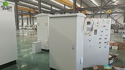
5. Electrical Faults Inducing Electromagnetic Vibration
- Three-phase voltage imbalances, phase loss, or poor electrical contact can lead to uneven magnetic field distribution within the motor, generating electromagnetic pulsations.
- Improper parameter configuration in the variable frequency drive (VFD) or excessive harmonic distortion can induce low-frequency resonance in the motor.
- Loose stator cores or inter-turn short circuits in the windings create unbalanced electromagnetic forces, triggering high-frequency micro-vibrations in the motor housing and base.


6. Inadequate Vibration Isolation and Environmental Adaptation
- Aging, hardening, damage, or detachment of motor vibration-isolation pads and rubber buffers results in a loss of their intended vibration-damping and noise-reduction functions.
- The dusty, humid, and condensation-prone environment typical of grain processing workshops can cause corrosion of the base's metal components, reducing their stiffness and compromising the structure's overall vibration resistance.
- The concentrated arrangement of multiple pieces of equipment—where adjacent conveyors and fans operate simultaneously—can lead to inter-equipment resonance, thereby compounding the vibration issues affecting the base.
In summary, abnormal vibrations in the motor base of grain steel silos are not caused by a single isolated factor, but rather result from the combined effects of various issues involving mechanical installation, transmission precision, foundation rigidity, rotor balance, electrical system integrity, and structural resonance. During on-site troubleshooting, one should adhere to the principle of proceeding "from the outside in" and "from the simple to the complex": First, inspect the anchor bolts and the foundation for any signs of looseness or deformation; second, verify the alignment precision and chain tension; third, conduct a single-unit no-load test to distinguish between faults inherent to the motor itself and interference originating from the load side; and finally, if necessary, utilize vibration spectrum analysis to identify the presence of specific resonance frequencies. For existing vibration issues, remedial measures—such as tightening fasteners, realigning components, structural reinforcement, dynamic balancing, or adjusting foundation rigidity—should be implemented based on the specific root cause; one must strictly avoid the blind installation of additional vibration-isolation pads, as this merely serves to mask the true underlying problem. Only by establishing a standardized mechanism for vibration monitoring and root-cause analysis can motor base vibration be suppressed at the source, thereby ensuring the long-term stability and reliability of grain turnover operations within steel silos.
Written by
Shandong Shelley Grain Steel Silo Co., Ltd
Editor Jin
WhatsApp : +86-18653877118
Email : shelley@cnshelley.com