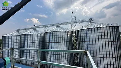
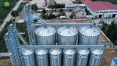
For flat-bottomed steel silos, the biggest advantage is their large storage capacity, while the biggest disadvantage is the tendency for material to stick to the walls during discharge, leading to incomplete discharge. With continuous technological advancements, the advent of negative pressure discharge has perfectly solved this problem. Today, Shelley Storage will explain why negative pressure discharge has become the optimal discharge method for flat-bottomed steel silos.
First, let's understand what negative pressure discharge is. The core principle of negative pressure discharge for steel silos is to use a fan to create a pressure difference between the silo interior and the pipeline, forming a high-speed airflow. This airflow, through its entrainment and carrying properties, transports the bulk material within the silo along the pipeline to the discharge port. Essentially, it's a specialized application of negative pressure pneumatic conveying in the unloading scenario of flat-bottomed steel silos. The entire process relies on the logic of "pressure difference → airflow movement → material gas-solid mixing and conveying" to achieve unloading, making it suitable for the structural characteristics of flat-bottomed silos, which have no slope and are prone to material accumulation.


Below, we will look at the eight reasons why negative pressure discharge is the best discharge method for flat-bottomed steel silos.
1. Thorough Clearing and Reduced Residue
The negative pressure discharge system for steel silos specifically addresses the key issue of residue in flat-bottom silos by addressing aspects such as power logic, suction design, and spatial adaptation. Each component works in concert to form a residue-free closed loop.
1.1. No Dead Zones in Unloading Power, Overcoming the Natural Limitations of Gravity Flow
- Traditional conical-bottom silos rely on gravity and slope for unloading. Flat-bottom silos lack slope, and gravity cannot drive material towards a single outlet, leading to large-area accumulation at the bottom. Negative pressure discharge, however, is powered by a directional, high-speed airflow created by pressure difference. This airflow can extend through pipes to any area on the silo bottom. As long as a suction port is installed, the airflow can reach that location and create suction, eliminating areas "not covered by gravity." This avoids material residue caused by a flat silo bottom from the source of power.
1.2. Multi-point suction port layout for full coverage unloading of the silo bottom.
- The negative pressure discharge system evenly distributes multiple suction ports on the silo bottom according to the silo's diameter and bottom area (8-16 or more for large-diameter silos). The spacing between the suction ports is controlled within the range where material can be drawn in by the airflow, and each suction port is independently controlled by a valve, allowing for sequential switching of operation.
- During operation, the suction ports are opened sequentially from the silo edge to the center, and from one point to another, allowing the negative pressure airflow to gradually cover the entire silo bottom area, eliminating blind spots and completely solving the problem of material residue at the silo edges and corners that cannot move to the outlet in traditional single-outlet unloading systems.
1.3. Active Airflow Entrainment: "Picking Up" Static Material Accumulation at the Silo Bottom
- Traditional mechanical unloading (such as silo sweepers) relies on the pushing action of mechanical components. However, due to uneven silo bottoms and material compaction, these components may become stuck, leaving a thin layer of material. In contrast, the high-speed airflow of negative pressure discharge has a strong entrainment effect. The airflow directly passes through the material accumulation layer at the silo bottom, actively "picking up" static material particles (including the thin layer of material adhering to the silo bottom) and enveloping them in the airflow. This forms a gas-solid mixture that is carried away, representing active unloading rather than the traditional "passive pushing" method, effectively removing any remaining thin layer of material at the silo bottom.
1.4. Fluidization Auxiliary at Suction Port to Overcome Material Clumping and Residue
- Issues Materials such as grain, cement, and fly ash, when stored in silos for extended periods, are prone to caking and adhesion to the silo bottom due to moisture absorption and compaction. This is one of the core challenges in preventing residue buildup in flat-bottom silos. Each suction port in the negative pressure discharge system is equipped with a fluidization nozzle/tube. During operation, low-pressure compressed air is introduced around the suction port to loosen the caked material and separate the material adhering to the silo bottom from the silo plate, restoring the material to a loose state.
- The loosened material can then be easily entrained by the high-speed airflow, avoiding the "cannot be blown away, cannot be sucked away" residue problem caused by material caking and adhesion.
1.5. The continuous penetrating power of negative pressure suction effectively cleans gaps and corners at the bottom of the silo.
- Steel silos have tiny structural gaps and corners at the bottom, such as seams between silo panels, the mounting base of the suction port, and the silo support structure. Traditional unloading methods struggle to reach these narrow areas, easily leading to trace residue. The continuous suction power of negative pressure, however, is penetrating, drawing air rapidly towards the suction port. Even small amounts of material in these gaps and corners are carried away by the flowing air, achieving residue-free cleaning of these small areas.
1.6. The system can operate continuously at low material levels until the silo bottom is completely emptied.
- The suction port of the negative pressure discharge system is positioned close to the silo bottom (with a spacing controllable between 5 and 10 cm). Airflow entrainment does not require a material layer; even if only a thin layer (a few centimeters thick) remains in the silo, the high-speed airflow can still effectively entrain it. Traditional mechanical unloading equipment, due to its structural limitations, cannot operate at low material levels and must reserve a certain material layer to prevent equipment wear, inevitably resulting in residue.
2. Gentle Discharge Process, Minimal Material Damage
The core reason for the low material damage achieved by the negative pressure discharge of steel silos is the use of flexible airflow conveying throughout the process. There is no hard contact, no strong compression, and no high-speed mechanical impact. Material particles only move in suspension within the airflow, and the conveying speed and collision force can be precisely controlled. This principle avoids the material breakage problems of traditional mechanical unloading, making it particularly suitable for materials with high breakage requirements, such as grains, pelleted feed, and fine chemical granules.
2.1. Flexible Airflow Bearing, No Hard Mechanical Contact or Strong Compression:
- The core problem of traditional mechanical unloading (such as scraper conveyors, augers, and bucket elevators) is the hard contact and strong compression between the material and the metal mechanical parts: the spiral blades of an auger push and compress the material, the scraper blades of a scraper conveyor scrape the material, and the buckets of an elevator impact the material. These hard contacts directly cause particle breakage and surface scratches.
- In negative pressure discharge, material movement is entirely achieved by high-speed airflow acting as a flexible carrier: material particles are dispersed and suspended in the airflow, contacting only the air and the smooth inner wall of the pipe throughout the process. There is no direct pushing/squeezing/scraping by mechanical components such as spirals, scrapers, or hoppers. This eliminates material damage caused by mechanical hard contact from the power source of the conveying process, which is the core key to low damage.
2.2. Controllable and "Suspended Uniform Speed" Reduces Particle Collision Force
- A major cause of material breakage is the violent collision under high-speed motion. However, the airflow speed in negative pressure discharge can be precisely adjusted according to the material characteristics (typically controlled at 18~25 m/s, and reduced to 15~20 m/s for fragile particles). Furthermore, the gas-solid mixture within the pipe exhibits stable, suspended uniform speed movement, eliminating the "rapid acceleration, rapid deceleration, and jamming" phenomena of mechanical conveying.
- Simultaneously, the material particles are dispersed in the airflow, increasing the spacing between particles and significantly reducing collisions. Even if a small number of particles come into contact with the inner wall of the pipe, the smooth finish (e.g., galvanizing, polishing) and the "light rubbing driven by airflow" rather than "forced mechanical impact" result in extremely light impact force, causing almost no particle breakage.
- Note: The conveying speed of negative pressure airflow is much lower than that of positive pressure pneumatic conveying (positive pressure is typically above 30 m/s), and negative pressure is "suction" rather than "push," eliminating the forced compression of material into the pipe and further reducing damage.
2.3. Completely enclosed with no drop, avoiding free-fall impact damage.
- In traditional unloading systems, material passes through multiple stages such as "bottom outlet → chute → elevator → hopper," involving multiple free-fall drops. When material falls from a height to the bottom of the metal hopper/chute, it generates a strong impact, causing particle breakage (especially in grains like rice, wheat, and corn, where the germ is easily damaged by impact). Negative pressure discharge utilizes a fully enclosed, horizontal/slightly inclined pipeline conveying system. Material is drawn in from the bottom suction port and moves entirely within the pipeline until it reaches the gas-material separation unit, eliminating any free-fall drop and completely avoiding impact damage from drops. Even in the cyclone separator within the gas-material separation unit, the material slowly slides down the inner wall (moving at low speed against the wall under centrifugal force) rather than falling directly, further reducing impact.
3. Simple System Structure and Convenient Workflow:
- Starting the negative pressure fan and fluidizing fan creates a stable negative pressure, and the fluidizing nozzle loosens the material at the bottom of the silo.
- The PLC opens individual suction port valves according to a preset program, and the high-speed airflow entrains the material, forming a gas-solid mixture, which flows through a branch pipe → the main manifold inside the silo → the main conveying pipeline outside the silo.
- The mixed flow enters the cyclone separator for coarse separation; the coarse material slides down to the airlock, while the airflow containing fine powder enters the bag filter for fine dust removal; the fine powder, after being blown off, also slides down to the airlock.
- The purified airflow enters the negative pressure fan and is discharged after passing through a silencer to meet emission standards.
- The airlock rotates, quantitatively pushing the material to the atmospheric pressure discharge end, completing the unloading.
- After unloading from a single suction port, the PLC automatically closes the valve and opens the next one, until the entire bottom of the silo is unloaded, with no residue throughout the process.
4. High Flexibility and Multi-Point Suction:
- This prevents materials from clumping or grading due to long-term static storage, and is especially effective for easily caking powdery materials.
- Multi-point material intake and discharge can be achieved through pipeline branching, adapting to the emptying needs of flat-bottomed silos with multiple areas of accumulated material. The pipeline layout is flexible and not limited by internal silo space.
- It does not rely on a conical bottom slope, thus requiring less sophisticated foundation design for flat-bottomed silos and avoiding the capacity loss and increased foundation costs associated with conical bottom structures.
5. Environmentally Friendly and Operationally Friendly
- Cyclone Separator (Coarse Separation): The core of the primary separation stage, with a cylinder diameter of φ800~2000mm. It uses centrifugal force to separate over 80% of coarse particles from the mixed flow. The material slides down the inner wall to the bottom discharge port, while the airflow containing fine powder enters the baghouse dust collector from the top outlet.
- Baghouse Dust Collector (Fine Dust Removal): The core of the secondary purification stage. The filter bags are made of antistatic/waterproof and oil-resistant material (antistatic for grain, waterproof and oil-resistant for cement/fly ash), with a filtration area of 50~500m². It traps fine powder in the airflow (filtration efficiency ≥99.9%), achieving a dust concentration of 10mg/Nm³ in the purified airflow, which directly enters the negative pressure fan.
- Cleaning Device: The baghouse dust collector is equipped with a pulse jet cleaning system (compressed air + pulse valve), which periodically blows off the fine powder from the filter bags, preventing filter bag blockage that could increase system pressure loss and reduce suction.
6. Facilitates Automation and Remote Control
- The negative pressure system is activated only when the material level is low or the material flowability is poor. At high material levels, gravity unloading can be combined to further reduce energy consumption.
- The system can be interlocked with elevators, flow valves, and other equipment. In case of failure, valves can be quickly closed to stop material flow, preventing silo buildup or equipment damage.
- There are no exposed high-speed rotating mechanical parts, reducing the risk of personal injury, making it particularly suitable for explosion-proof or dust-sensitive working environments.
7. Strong Long-Distance and Spatial Conveying Capacity
- Negative pressure conveying can utilize flexible pipeline layouts to easily achieve conveying distances of hundreds of meters, and can be lifted to a certain height or bypass obstacles. This is particularly advantageous for sites with dispersed layouts or limited space.
- Short-distance conveying (≤100m) has low energy consumption, with an output energy consumption of approximately 0.3-0.5 kWh/ton, and maintenance costs as low as 0.1 RMB/ton, significantly lower than mechanical conveying methods.


8. Relatively Economical Energy Consumption
- Although pneumatic conveying itself requires electricity to create a vacuum, compared to the high maintenance costs of bottom-mounted mechanical systems and the high-pressure blowers required for positive pressure conveying (which may consume even more energy), negative pressure systems are often more advantageous in terms of overall operating costs, especially for medium conveying distances and the handling of various materials.
9. Precautions:
- For materials with high moisture content, easy adhesion, or easy agglomeration, special design is required (such as flow aids, specific suction nozzles), otherwise the effect may be affected.
- There are certain limitations on the conveying capacity of a single system and its ability to handle oversized particles.
- Reliable gas-solid separation devices (such as cyclone separators, bag filters) and vacuum power equipment (Roots vacuum pumps, etc.) are required.
10. Conclusion
For flat-bottomed silos, negative pressure discharge provides a clean, efficient, low-maintenance, highly flexible, and environmentally friendly solution. It utilizes a combination of "fully controllable negative pressure airflow + active entrainment + fluidization assistance" to specifically address all residual causes in flat-bottomed silo unloading. It eliminates the dependence of gravity on the silo's slope, solves the space coverage problem through multi-point layout, and addresses material caking and adhesion through fluidization and entrainment. Ultimately, it achieves thorough unloading with no dead corners, thin layers, or micro-gaps at the silo bottom, significantly reducing material residue. It perfectly compensates for the inherent limitations of flat-bottomed silos in gravity-flow discharge (the inability to completely empty by gravity), transforming the disadvantages of the simple flat-bottom structure into advantages of easy cleaning and maintenance. It is particularly suitable for modern industrial scenarios with high requirements for material integrity, system hygiene, and automation. Through the above explanation, we should now have a very solid understanding of the negative pressure discharge method used in flat-bottomed steel silos. If you have any further questions, please feel free to contact us.
Written by
Shandong Shelley Grain Steel Silo Co., Ltd
Editor Jin
WhatsApp : +86-18653877118
Email : shelley@cnshelley.com