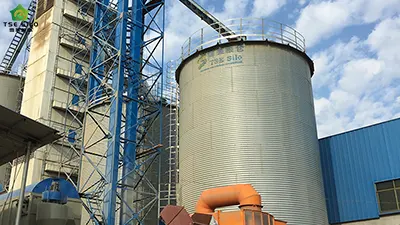
Grain steel silos utilize pneumatic conveying systems, offering advantages such as a sealed, dust-free environment, flexible layout, and high automation, making them widely used in grain depots, flour mills, and feed mills. However, grain, as an active organic material, has low particle strength, is easily broken, and highly hygroscopic, and the dust generated during conveying poses an explosion risk. Compared to industrial powders such as fly ash and cement, pneumatic grain conveying has drastically different requirements in system design, operation, maintenance, and safety management. Neglecting key details can lead to anything from minor issues like pipe blockage and excessive grain breakage to serious consequences such as dust explosions or damage to the steel silo structure. Therefore, based on engineering practice in the grain industry, Shandong Shelley has summarized the following nine important considerations to help on-site personnel safely, efficiently, and with low energy consumption complete pneumatic conveying operations in grain steel silos


1. Strictly Control Grain Moisture Content to Prevent Pipe Blockage and Mold
Grain moisture content is a core control indicator for the smooth operation of pneumatic conveying and the safety of storage. High moisture content directly leads to poor flowability, pipe wall adhesion, and caking/blocking within the storage silo. It also causes condensation, overheating, and mold growth, severely impacting conveying efficiency and grain storage safety.
1.1. Moisture Content Control Standards for Different Grain Types
- Wheat: <=13.0% for pneumatic conveying upon entry into the silo.
- Corn: <=14.0% for pneumatic conveying upon entry into the silo.
- Rice: <=14.5% for pneumatic conveying upon entry into the silo.
- Soybeans: <=13.0% for pneumatic conveying upon entry into the silo.
Exceeding these ranges significantly increases the internal friction angle of the grain, raises the resistance to pneumatic conveying, and exponentially increases the probability of pipe blockage.
1.2. Direct Impact of High Moisture Content on Pneumatic Conveying
- The grain surface becomes sticky, easily adhering to the inner walls of pipes, bends, and diameter changes, forming wall adhesion and narrowing, gradually leading to pipe blockage.
- Reduced fluidity, making arching and bridging more likely to occur inside the silo, and making it difficult to discharge from flat-bottomed silos.
- Imbalance in the solid-to-gas ratio, resulting in large system pressure fluctuations, increased fan load, and increased energy consumption.
1.3. Relationship between Moisture Content and Mold and Condensation in Silos
- High-moisture grain easily respires and releases heat in sealed steel silos, creating a temperature difference between the inside and outside of the silo, leading to condensation on the silo walls and roof.
- Condensation droplets falling back onto the grain surface can cause localized increases in moisture content, triggering heating, mold, and clumping.
- During long-term storage, for every 0.5% to 1% increase in moisture content above the standard, the safe storage period of the grain pile is significantly shortened.
1.4. Humidity Control Measures for Pneumatic Conveying Systems
- Cleaning, screening, and drying processes are implemented before grain enters the silo to ensure the moisture content of incoming materials meets standards before entering the conveying system.
- Air compressors are equipped with drying and filtering devices to reduce the moisture content of compressed air and prevent moisture from being carried into the silo.
- Conveying should be reduced or suspended appropriately in rainy, foggy, or high-humidity environments to prevent external moisture from entering the silo.
- The silo roof ventilation and circulating fans are operated regularly to reduce humidity inside the silo and maintain a stable moisture content in the grain pile.
1.5. Daily Monitoring Requirements
- Moisture content must be sampled and tested before each batch of grain enters the silo. Grain that does not meet the requirements is strictly prohibited from entering the pneumatic conveying line.
- Temperature, humidity, and moisture monitoring points are set up inside the silo to monitor changes in grain pile moisture in real time.
- If an abnormally high local moisture content is detected, feeding must be stopped immediately, and ventilation and repositioning measures must be taken.
2. Conveying air velocity must be within a reasonable range for grain suspension velocity.
Grain is a granular material; if the air velocity is too low, it will cause settling and blockage of the pipes; if it is too high, the breakage rate will soar.
2.1. Basic Range of Grain Suspension Velocity
- Wheat: 7.5-9.0 m/s.
- Corn: 9.0-11.0 m/s.
- Rice: 6.5-8.5 m/s.
- Soybean: 10.0-12.0 m/s.
2.2. Recommended Design Velocity for Pneumatic Conveying
To ensure continuous and stable conveying, the actual air velocity should be 1.3-1.6 times the suspension velocity. Commonly used ranges:
- General grain conveying air velocity: 18-26 m/s.
- Horizontal pipe sections should be closer to the upper limit, and vertical pipe sections can be closer to the lower limit.
2.3. Hazards of Excessively Low Air Velocity
- When the air velocity is < 16 m/s, grains are prone to deposit at the bottom of horizontal pipes, gradually forming blockages.
- Localized material accumulation will lead to a sudden increase in pipe resistance, large system pressure fluctuations, and fan overload tripping.
- Uneven discharge, resulting in localized material accumulation and arching within the storage silo.
2.4. Hazards of Excessive Wind Speed
Grain grains collide with pipe walls and bends, significantly increasing the breakage rate, resulting in more broken rice, broken grains, and shriveled grains, affecting grain quality.
- Accelerated wear and tear on pipes, bends, and diameter changes, shortening service life.
- Redundant operation of fan airflow and pressure increases power consumption by 15%–40%.
2.5. Key Points for On-Site Control
- Use variable frequency fans to fine-tune the wind speed according to grain type and conveying distance, stabilizing it within the set range.
- Avoid sudden changes in pipe diameter and excessive sharp bends that could cause a sudden drop in local wind speed.
- Regularly monitor the actual wind speed inside the pipes to ensure it does not deviate from the design value.
The wind speed in pneumatic grain conveying is a key parameter determining whether pipe blockage occurs, the breakage rate, and energy consumption. Wind speeds below the suspension velocity will cause settling and blockage, while excessively high wind speeds will exacerbate grain breakage, increase pipe wear, and increase fan energy consumption. Therefore, it is essential to strictly control the wind speed within a reasonable range for grain suspension.
3. Controlling the Solid-Gas Ratio to Ensure Stable Conveying and Prevent Pressure Buildup
Grain pneumatic conveying is mostly dilute-phase positive pressure conveying:
3.1. Commonly Used Solid-Gas Ratio Range for Grain Pneumatic Conveying
- Dilute-phase positive pressure pneumatic conveying (the mainstream form of Shelley grain steel silos): Solid-gas ratio is 3:1 to 8:1.
- Short distances, mainly straight pipes: 6:1 to 8:1 is acceptable.
- Long distances, many bends: 3:1 to 5:1 is recommended.
3.2. Corresponding System Working Pressure
- Normal working air pressure: 0.03 to 0.08 MPa.
- Allowable pressure fluctuation range: +(-)0.02 MPa.
- Exceeding 0.10 MPa is considered abnormal pressure buildup, requiring immediate investigation of material blockage risk.
3.3. Hazards of an Excessively High Solid-Gas Ratio
- Excessive grain carried per unit of gas, insufficient air velocity, grain sedimentation within the pipe.
3.4. Problems with Low Solid-to-Gas Ratio
- Excessive airflow and insufficient grain conveying capacity result in low system energy efficiency.
- High-speed tumbling and collision of grain grains within the pipe increases breakage rate, affecting grain quality.
- High no-load loss of the blower increases power consumption and operating costs.
3.5. Key Points for On-Site Control
- Quantitative feeding via rotary unloader to stabilize the feed rate and avoid sudden fluctuations.
- Variable frequency drive (VFD) for the blower to adjust airflow in real-time according to pressure, maintaining a reasonable solid-to-gas ratio.
- Strictly prohibit sudden increases in feed rate to prevent material-gas imbalance and instantaneous blockage.
- Closely monitor air pressure and current during operation; promptly reduce feed and investigate if persistently high levels are observed.
The solid-to-gas ratio is a core parameter for flow matching, pressure stability, and continuous operation of a grain pneumatic conveying system, directly reflecting the amount of grain that a unit of gas can carry. A ratio that is too high can easily cause pipe blockage and pressure buildup, while a ratio that is too low will result in wasted airflow and high energy consumption. It must be controlled within a reasonable range based on the conveying distance and grain type.
4. Matching the parameters of the bottom gasification/fluidization device to grain flowability.
Flat-bottomed silos must be equipped with gasification plates/fluidization troughs; otherwise, dead zones and stagnant material are prone to occur:
- Fluidization airflow: 0.2-0.4 m3/(m2·min).
- Fluidization pressure: 0.03-0.05 MPa.
- The arrangement area should not be less than 12%-15% of the silo bottom area.
- After meeting the standards, the discharge smoothness rate can reach over 95%. Insufficient fluidization will cause bridging and arching.
5. Minimize bends in pipeline layout to reduce grain breakage and resistance.
- Horizontal pipes should be as short as possible, with no more than 2 bends per 50m.
- Bend radius of curvature R >=6D (more than 6 times the pipe diameter).
- Bends are the most severe locations for grain breakage and pipeline wear, with breakage rates potentially exceeding 60%.
- Avoid sharp 90o bends and vertical sharp drops/upwards to prevent impact breakage.
6. Strictly control silo top pressure to prevent silo collapse or bulging.
Grain density is low, and dust is light, making silo pressure highly susceptible to fluctuations:
- Normal operating silo pressure: +(-)0.3-0.8 kPa.
- Positive pressure protection valve operating pressure: +1.0-+1.5 kPa.
- Negative pressure protection valve operating pressure: -0.5 kPa.
- Silo top dust collector ventilation volume >=1.1 times the conveying air volume to prevent pressure buildup.
7. The system must be tightly sealed to prevent air leakage and conveying failure.
- Flanges, expansion joints, and unloaders are the main points of leakage.
- The clearance of the rotary unloader should be <=0.15mm.
- When the system air leakage rate is >10%, the conveying capacity will decrease by 20%–30%, and insufficient air velocity will directly block the pipes.
- Inspect the flange bolts, flexible joints, and observation door seals every shift.
8. Reasonable material level and feeding sequence to avoid uneven loading and silo settlement.
- The feeding height should not exceed 90% of the designed material level.
- Prohibit long-term concentrated feeding from one side or single point to prevent uneven pressure on the silo wall.
- For large flat-bottom silos, it is recommended to use multiple feeding points with a feeding height difference <=1.5m.
- Initial grain loading should be completed in 2–3 stages, with each stage allowing the grain to settle and observe settling, avoiding filling the silo all at once.


9. Dust Explosion-Proof and Grain Safety Standards Must Meet
Grain dust is flammable and explosive:
- Internal temperature control: <= 50oC; alarm and shutdown if exceeding 60oC.
- Dust concentration must be far from the lower explosive limit; local dust accumulation is strictly prohibited.
- Electrical equipment must be dust explosion-proof; grounding resistance <=4ohm.
- Fire arrestors and explosion relief devices must be installed on the silo roof; open flames and static sparks are prohibited.
Shelley grain steel silo pneumatic conveying is not simply a matter of "blowing it in," but a sophisticated engineering project involving material characteristics, airflow parameters, equipment selection, explosion-proof safety, and silo protection. The above nine precautions are interconnected—from strictly controlling conveying speed and pressure to prevent grain breakage, to ensuring the reliability and effectiveness of dust removal and explosion relief devices; from strictly preventing condensation and mold growth, to standardizing start-up, shutdown, and cleaning procedures; each is based on lessons learned from actual failures. Shelley recommends that operators and managers memorize these key points, develop standard operating procedures, and regularly conduct system checks (pressure, flow rate, airtightness, dust concentration, etc.). Only by implementing measures to prevent breakage, blockage, explosion, grading, and condensation in every conveying process can the advantages of pneumatic conveying—cleanliness and flexibility—be truly realized, ensuring the long-term safe and economical operation of grain steel silos. We hope this information compiled by Shelley Storage will be helpful for your future use of grain steel silos.
Written by
Shandong Shelley Grain Steel Silo Co., Ltd
Editor Jin
WhatsApp : +86-18653877118
Email : shelley@cnshelley.com